
Injection Mold Manufacturing
How a small or medium injection mold moves through the tooling workshop — from the first drawing review to the packed and inspected tool sitting on a pallet.
Drawing Review & DFM
Before any quote is confirmed, we read the drawings. We check the part for wall thickness consistency, draft, undercuts, gate positions, ejection strategy and expected shrinkage. If information is missing, we ask. If a feature is unlikely to mold cleanly, we say so and propose an alternative.
You receive a short DFM note back — sometimes a page, sometimes a marked-up screenshot. That note becomes the record of what we agreed before steel was cut.
Mold Design
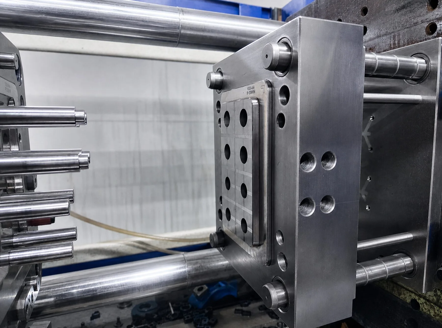
Mold design is done at the tooling workshop in UG / NX (with 2D drawings in AutoCAD). We work out parting line, gating, ejection and cooling with the same engineer who reviewed the part — not a separate design office that never sees the workshop.
Before machining starts, we send you the mold layout, gate positions, ejector plan and cooling plan for approval. Changes at this stage are cheap; changes after steel is cut are not.
Steel Preparation & Machining
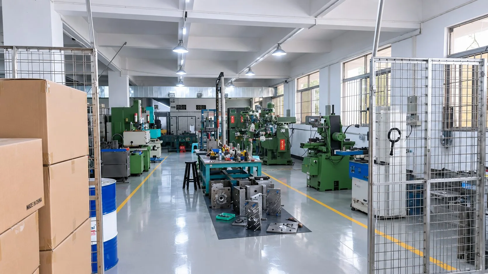
Steel is selected together with you — P20 / 1.2311 for prototype and mid-life tools, 718H / 2738 for pre-hardened production, S136 / 2083 for optical or high-polish cavities, H13 / 1.2344 for high-wear zones. Material certificates travel with the tool.
CNC machining is done by established machining partners. The workshop tooling engineers set the machining strategy, review the CAM programs and inspect components before EDM, fitting and assembly.
EDM, Fitting & Polishing
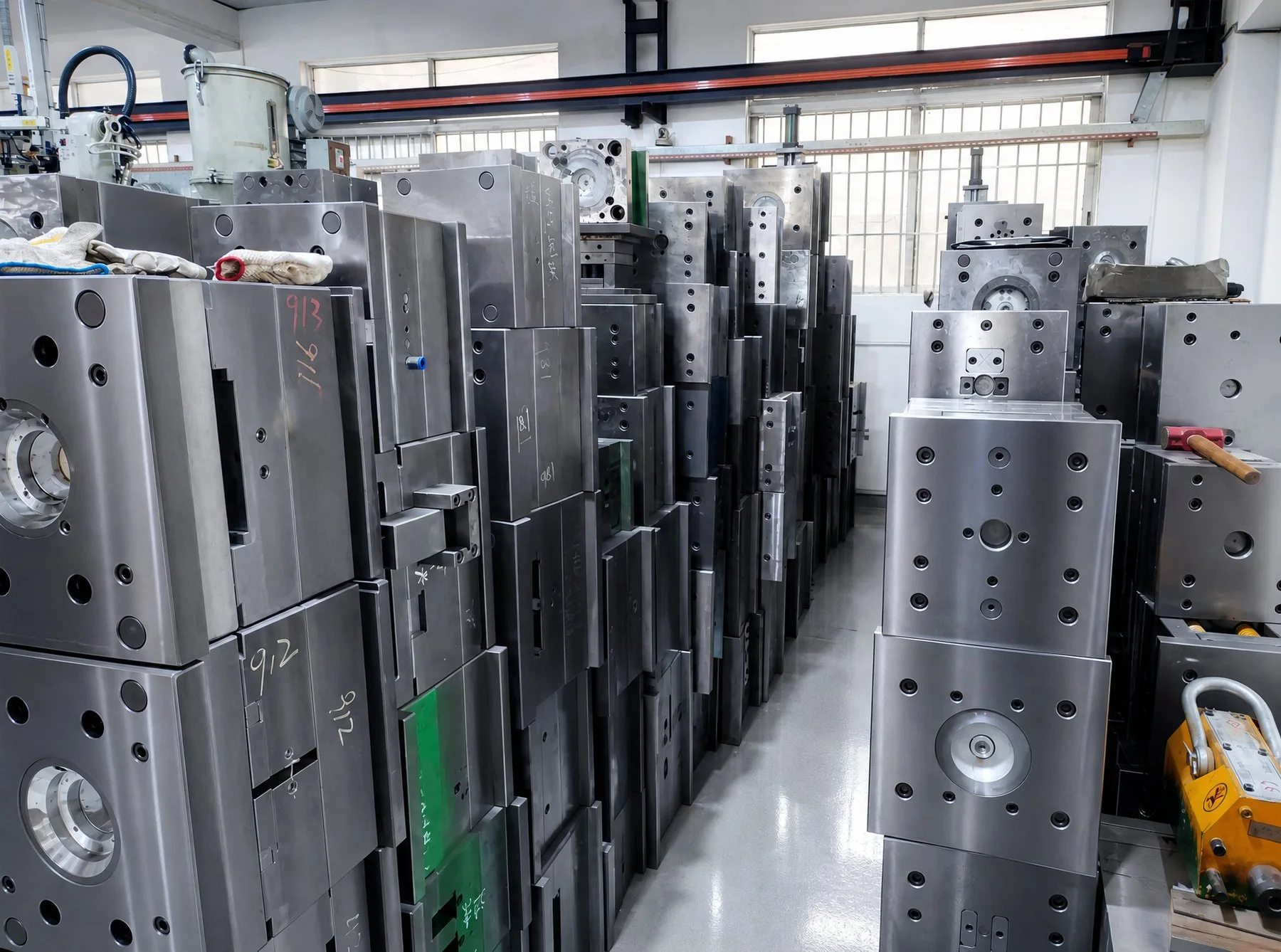
EDM is at the tooling workshop. Sinker EDM handles ribs, sharp corners, logos and text; wire EDM opens ejector holes and precision slots. Electrodes are prepared and inspected before burning.
Fitting and polishing are handled by mold makers who have done this work for years. Parting lines, shut-offs, slider faces and cavity surfaces are worked by hand until they meet the drawing and the surface spec.
Assembly & T1 Trial
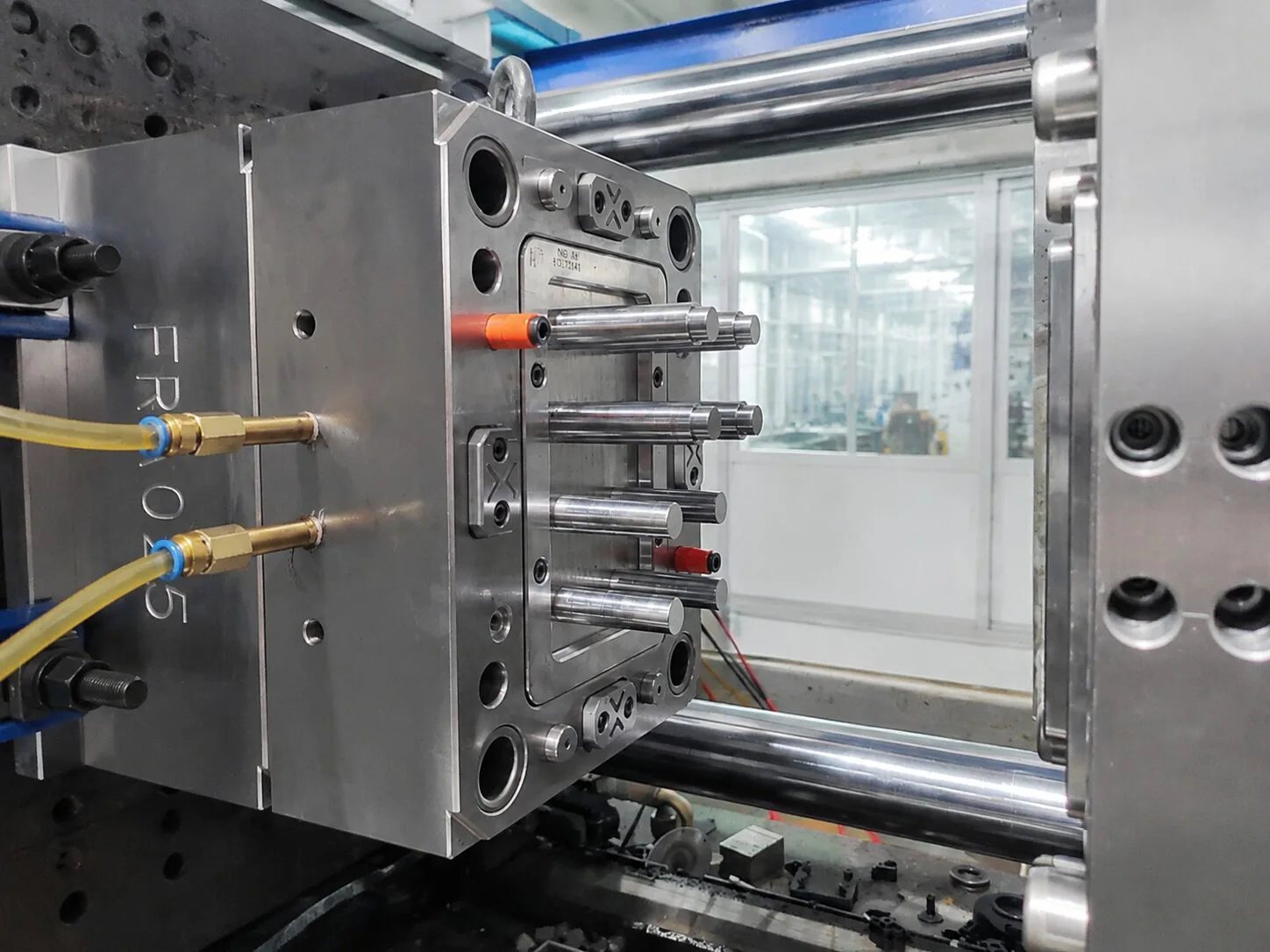
Assembly brings core, cavity, slider, lifter, ejector and cooling together with the mold base. Every water line is pressure-tested; every slider is cycled by hand before the tool goes on a machine.
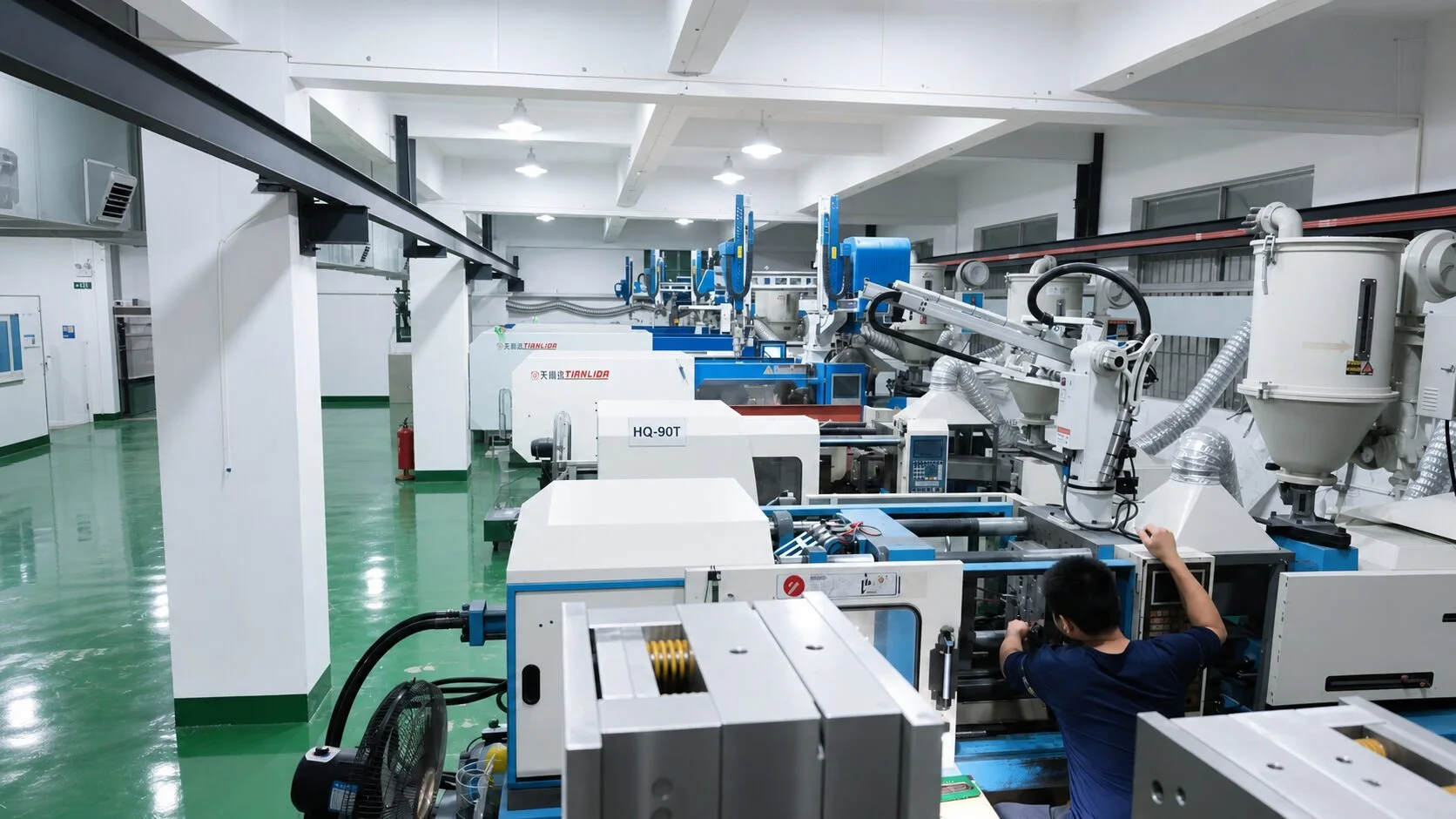
T1 trial is done at the tooling workshop on the workshop’s 90T–200T injection molding machines. You receive:
- Sample photos of the first-shot parts
- A short trial video showing mold opening and part ejection
- Trial report — process conditions, cycle time, observations
- CMM data or caliper measurements on critical dimensions
If the parts need a T2 (which is normal), we run T2 after the corrections and send fresh samples before the mold ships.
Final Inspection, Packing & Shipment
Before packing, the mold is cleaned, oiled and photographed — closed, opened, both halves, and the runner side. Samples travel with the mold. Documents travel with the mold.
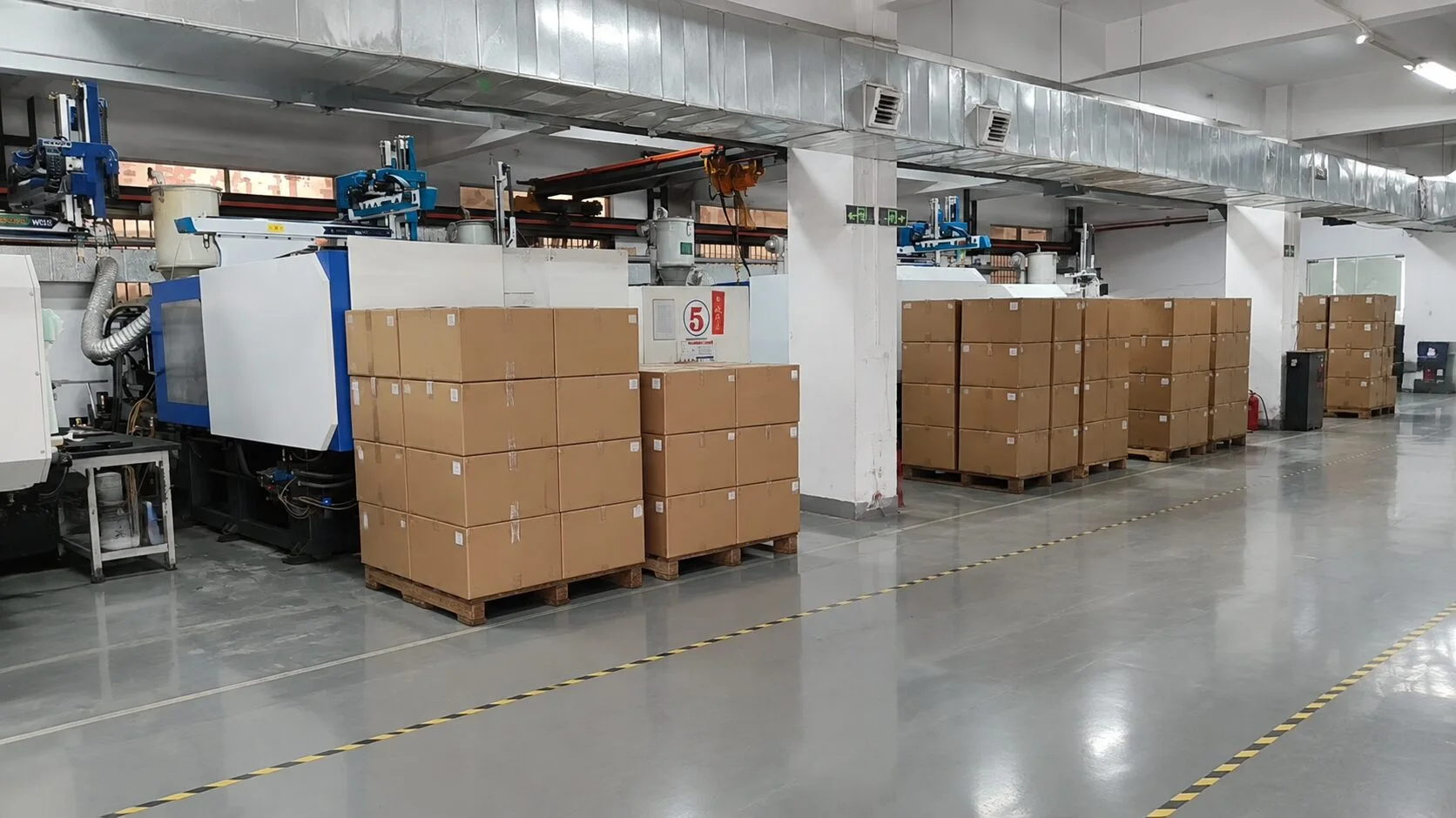
Packing is a proper wooden case with steel banding, silica gel and rust protection. The tool is photographed inside the crate before the lid goes on.
- Final photos: closed, opened, both halves, runner, cavities
- Material certificates for all mold steels
- Heat treatment and hardness report
- T1 trial report + samples in a labeled bag
- CMM inspection sheet for critical dimensions
- Packing list, HS code, commercial invoice for customs
Realistic Delivery Windows
Lead times below assume drawings are frozen at kick-off and steel is available. We confirm dates in writing after drawing review — never before.
| Type of mold | Typical lead time (design → T1) |
|---|---|
| Prototype mold, 1 cavity, part < 150 mm | 18 – 25 working days |
| Single-shot production mold, 1 cavity, part 150 – 300 mm | 30 – 40 working days |
| 1+1 or 2-cavity production mold with sliders | 35 – 45 working days |
| Multi-cavity production mold (up to 8 cavities) | 40 – 55 working days |
| Mold repair / insert replacement | 7 – 15 working days after part receipt |